Ramble
The Turing ticker device requested a ticker tape parade.
"It's to come right after I reach infinity, a task for which I'm made! Warm up the ramparts, and prime the canon's three. For its surely not long now" squeaked the little ticker teeth.
Continuing with its incessant ticking, onward the machine beamed.
An outsiders perspective was required to show its folly. For it was obvious to those with perspective that productivity was upon a repeating circular loop.
Update
Its been roughly a month now since I did much1 to this site. Its normal for my interest levels continue to ebb and flow. I do want to pick it up again and continue building but I am not finding the focus to prioritise it.
With this post I am committing my progress so far with the occlusion culling. I will build a reference implementation for this extending my three.js scene work as I get the time.
Something that has taken my interest in the last window is another complex problem that has been bothering my project at work.
Let me set the scene,
Problem Space
Commonly, a road network is modelled as a set of centerline's234. By definition, a centreline runs through the middle of something and in this case its an imaginary line running down the middle of a road carriageway.
A good centerline,
- has each point defined as an , and and in the case of Australia, it should be in GDA2020 in the appropriate MGA5 Zone; and
- must allow a distance calculation that represents the real world running distance along the carriageway that if you measured (or drove) along from the start to that marker, you would be at the corresponding , and ; and
- is not overly descriptive, redundant points should not be defined on the line; and
- has dampening at slip lanes, turning lanes and ramps start and end along the carriageway, over-fitting to these results in a zig-zag centreline that is overly long. This is subjective, but it shouldn't fail the "feels wrong test". It is important that the centerline does not look wrong when the pavement and lane geometry is not available to explain some random deviation in the centreline that you would not make while travelling down the road.
Context
It would be handy to have a machine that the design process could pass a model (BIM) and an indication of where the centerline's should be and set of centrelines and relevant features are created. When the design process inevitably takes a step in design, moving an alignment, the new model can be processed to update the centerline.
Conceptually, its possible create this in a number of ways as long as the model is classified sufficiently. My initial thoughts are,
Consider the pavement wearing course geometry
The dataset for pavements are subject to individual digital engineering decisions varying from project to project. Its very likely this will be a large polygon representing the road surface.
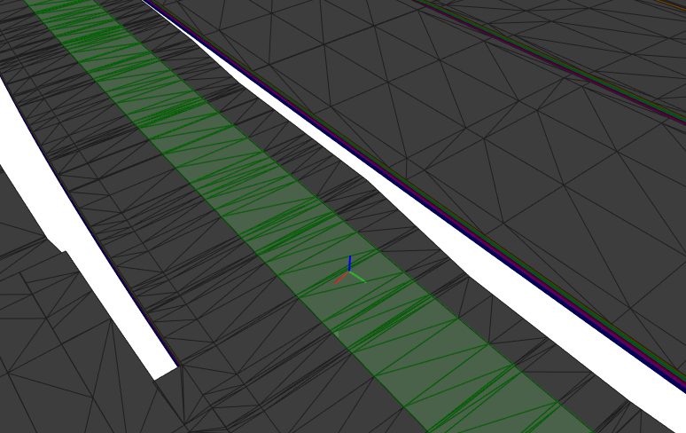
A reasonable project would decide to provide some level of meta-information on subsections of the polygon representing carriageway's that can be aggregated. The road surface polygon could be processed to find the long sections and an optimisation approach could be taken to fit the appropriate sets of centreline's that best represent the road network.
Consider the line marking geometry
All jurisdictions in Australia derive or are adjacent to the the Austroads standards for line markings (for obvious reasons). A over simplification is that carriageway's have shoulders marked by solid lines and carriageway lane's are separated by broken lines.
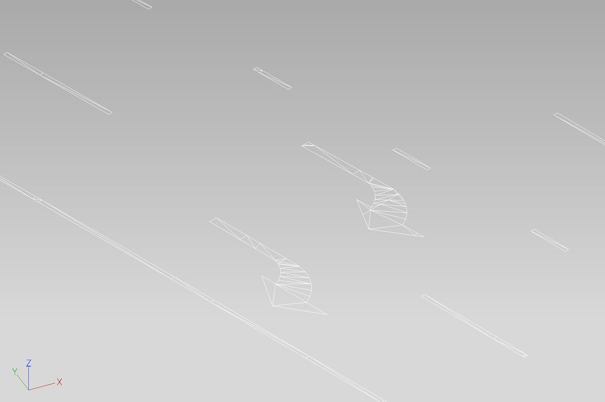
A reasonable project would likely model these as a central set of control lines and symbol locations that are utilised in GIS, BIM and 2D drawing sheets. Practically, the would lag the design of the road base and pavement sections and their 3-dimensional location is ultimately informed by draping what is required onto the road pavement surface aligned to the standards. For BIM, the road line markings are a set of polygons that are coincident with the road pavement surface that represent the required road line marking's.
Consideration
This is roughly how my brain worked thinking about these,
| Approach | Pavement Geometry | Line Marking |
|---|---|---|
| Summary | Fit Centrelines to Pavement Polygons | Calculate Centrelines from Line Marking Geometry |
| Pro's | - Seem's highly flexible if the approach is a completely unsupervised fit of a centreline to the pavement geometry | - Allows a centreline that is likely best for "feels wrong test" |
| Con's | - Pull off lanes, access roads and other features will skew this without a lot of effort | - Likely more variability to how line markings are modelled from project to project. |
| Personal Bias | - I am interested in the optimisation problem and the ability to fit a good line to geometry is something I need in the long term. - I worry that this will become a whole project of its own that I don't have time to do this properly - I can cheat in the dataset I am working with anyway (you will notice the example image has the lane split as a polygon already. I doubt this common) |
- Same interesting problem turning polygons into a representative line. - I think a result that I can demonstrate using the line markings as overlay will get better acceptance |
| Volume of input data | High | Medium |
| Speed to value | Slower | Faster |
Ultimately, I settled on a Line Marking based supervised approach and to focus on the method of turning polygons representing solid and broken lines into a reliable centerline.
My Approach
I decided to beeline straight to value so I could get this done and move on. I broke my roads into segments and I needed three main functions,
- A function to calculate the corresponding line for a segment coincident with a line marking (solid or broken) - consider a two lane carriageway, the broken line down the centre is where I need my line; and
- A function to calculate the centreline between two line markings (solid or broken) - consider a single or three lane road, in these cases I need a new line between two of the lane lines; and
- A function that figures out how to join centerline's at intersections or ramps.
The next step was to devise a JSON schema to specify the line markings to consider. This is a mapping into the global identifiers in the 3D IFC file containing the geometry.
The following is an example of how I am doing this,
{
  "02943": {
    "road":"02943",
    "links": ["L540", "L545"],
    "side":"L",
    "code": "MC98",
    "type": "ROAD",
    "name": "Waffle Street",
    "segments": [
      {
        "ifc": "JWMPLA-JWM-JWM-GD-M3D-100090",
        "point_count": 100,
        "segment_list" : [
            ---
            <list of segment data>

            ---
        ]
      }
    ],
    "features": {
        ---
        <list of feature data>

        ---
    }
  }
}
I then specified the segment data. The simple cases are where the centerline can be calculated from the polygons making up a solid or broken line. Its a matter of finding a sequence of good representative points coinciding to the centre of the line geometry.
    {
        "type": "line",
        "link_reference": "L540",
        "id": "2HyNQz__CstJyd4UZL6e3J"
    },
    {
        "type": "line",
        "link_reference": "L545",
        "id": "3moP0hhhzFk2WOsTnsgj6X"
    }
The cases where there is an odd number of lanes (1 lane, 3 lanes etc) are similar to the simple line case, but two centrelines for solid or broken lines need to be calculated, then the centre of those needs to be found. I borrowed and to represent the input lines.
    {
        "type": "centre_line",
        "link_reference": "L540",
        "u_id": ["9IfuWNndEiX_wow4KjaCrF","8aCENwaQZmTyg3glJf$Bnu"],
        "v_id": ["0Jj_nWJmHG2rRrjgURkz_e"]
    }
The last function I required was a method to link two or more centerline's to model a road network. For this, I kept it minimal and calculated what I need in code. In this case, I am saying that my current road (02943-L) branches from another road (82043-L) with an additional segment coincident at 30 degrees and this branch defines the current road's start (road running distance of 0).
"branch_from": {
    "rrd": 0,
    "join_road": "82043",
    "join_side": "L",
    "join_angle": 30
}
Simplifying a lot of the detail, I read the JSON using python, and leverage ifcopenshell to extract and process the IFC element representation geometry to create and connect a road network.
Results
The method works surprisingly well and for my network, it has been flexible enough to handle some interesting cases for a major road upgrade.
The following figure is a GIS render of example input IFC.
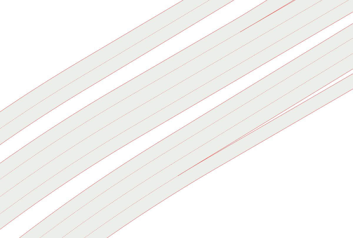
These control lines contain , and coordinates. The top most example is a typical Australian road with a left and right lane on a single carriageway. The middle and the bottom are more complex examples like those that I needed to capture containing multi-lane carriageways with ramps entering an exiting.
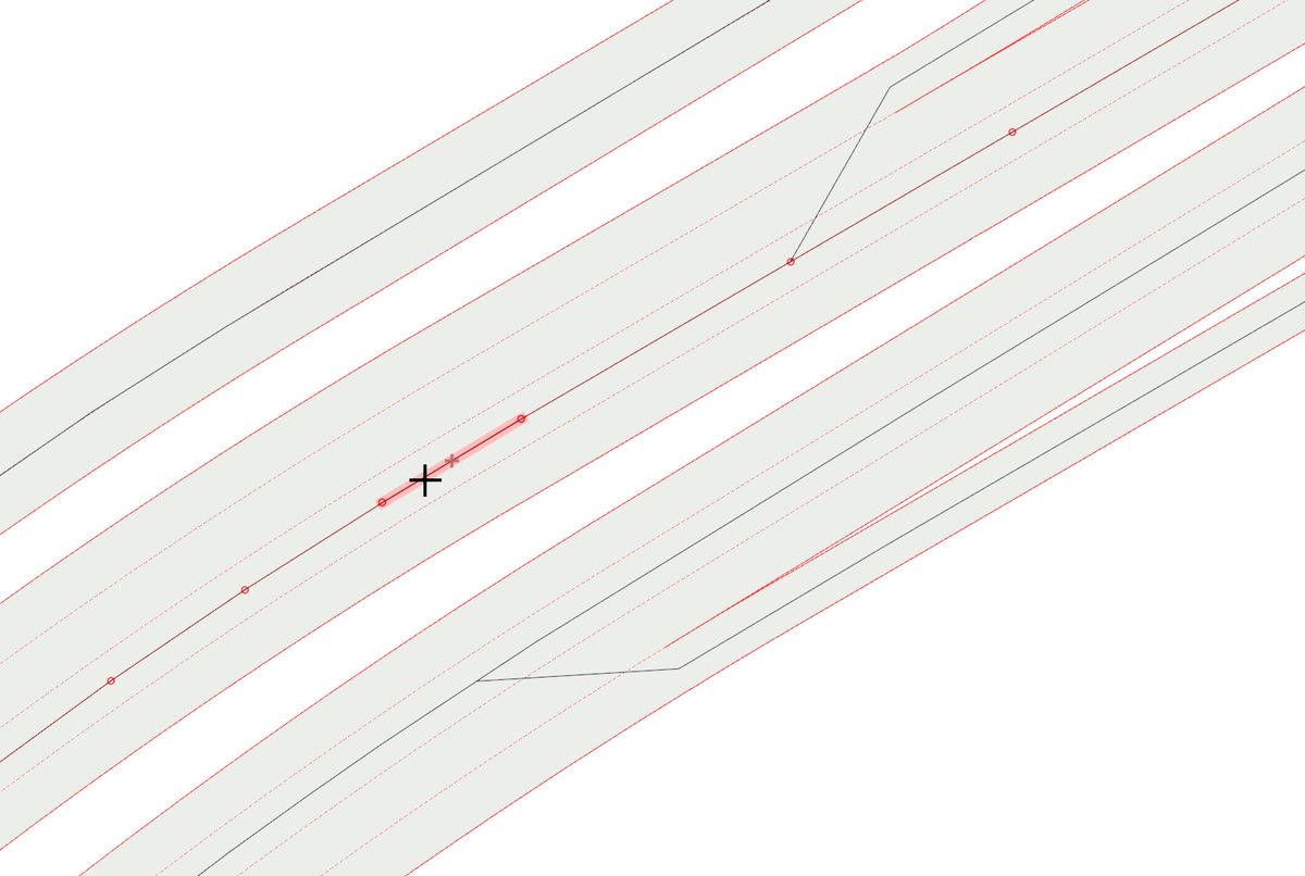
Running the process over the IFC and the segment configuration leads to the following centrelines being generated.
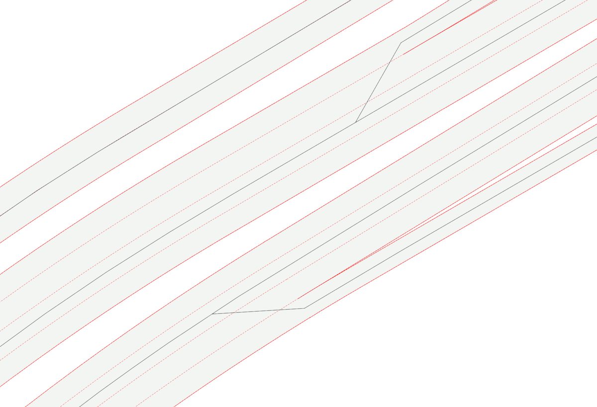
The top typical example has what you would expect for a centerline, its completely coincident with the broken line down the middle of the carriageway. The multilane lane carriageways are a lot more interesting. You will notice the middle centerline appears to be offset but it is motivated by the "feels wrong test" and not wanting to skew the centerline left or right when the ramp connects.
Lastly, its very easy for the generated lines to be overfit and to result in very complex geometry. In my case, the lines that were based on the centre of each broken dash were overly complex and in some cases looked quite wrong at the joins. To address this, I have looked at the sections between the vertices and removed majority of the vertices if they do not contribute to the overall shape of the centerline. You can see this viewing the vertices in the GIS.
So that is it. This has been distracting me in my spare time but making progress on something relevant and interesting is nice.
I have already scaled this to many more features and I am in the process of applying it to a large project here in South Australia.
A pivot back to this site is due for me I think.
Footnotes
-
Anything. ↩
-
Map Grid of Australia. A decent layout from Esri regarding the MGA ↩